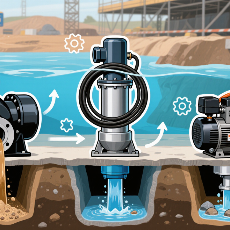
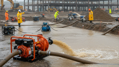
Choosing the right Dewatering Pump can determine whether a project stays productive or loses valuable hours. Excavation pits, flooded basements, tunnels, and construction sites all present different water conditions. Clear groundwater behaves differently from muddy runoff filled with sand, clay, or small stones.
A reliable choice begins with measured site information. Check the required flow rate, total head, discharge distance, suction conditions, and available power supply. A pump moving 200 gallons per minute may still fail when the discharge hose rises sharply. Hose diameter matters too. A narrow, twisting hose can create unnecessary friction and reduce actual performance. These details are easy to overlook.
Pump construction also deserves careful attention. Cast iron components often suit abrasive water, while lighter materials may work better for short-term, clean-water tasks. Diesel, electric, and hydraulic models each have practical strengths. Electric pumps can operate quietly, but unstable power creates risk. Diesel pumps offer mobility, although fuel handling and ventilation require discipline. Manufacturer performance curves provide useful guidance, yet field conditions rarely match laboratory figures perfectly.
No selection guide is flawless. Water levels change, sediment increases, and equipment may be moved without proper recalculation. Experienced operators inspect intake screens, monitor vibration, and keep backup drainage plans ready. They also question optimistic flow estimates. A dependable supplier should explain limitations, maintenance intervals, and realistic operating costs, not only highlight maximum capacity. This guide examines those decisions closely, helping readers compare pump types and select equipment with greater confidence. Good planning matters. Yet careful observation on site remains essential.
How to Choose the Right Dewatering Pump?
Choosing a dewatering pump starts with defining its duty, not selecting equipment by pipe size alone. Flow rate describes how much water must move within a given period. Measure the expected inflow, including rainfall, groundwater, leakage, and sudden surges. A dry excavation can change quickly after heavy rain.
Total Dynamic Head, or TDH, is equally important. It includes vertical lift, pipe friction, bends, valves, discharge restrictions, and outlet pressure. For example, a pump lifting water 8 metres may face 5 additional metres of system losses. The required TDH is therefore about 13 metres. Field measurements are better than assumptions, although they are not always perfect.
Tips: Record the water level at the pump inlet and discharge point. Check pipe length and diameter carefully. Count every bend and valve. Add a 10–20% design margin to both flow and head when conditions may vary. This margin helps handle muddy water, changing levels, clogged screens, and imperfect estimates. Do not make the margin excessive. Oversizing can cause unstable operation, wasted energy, and poor control.
I have seen projects fail because the advertised flow was accepted without checking performance at the actual TDH. Request a pump curve and identify the duty point where flow and head intersect. Then compare that point with the site requirement. Recheck the calculation after installation. Real conditions often expose details missed on paper.
Choosing the right dewatering pump starts with the solids, not the advertised flow rate. In field work, muddy water can carry gravel, broken concrete, roots, and sharp mineral fragments. A pump passage of 25–100 mm helps reduce blockages when particle size changes during a shift. Measure the largest solids, not the average. One oversized stone can stop a narrow impeller quickly.
For light sediment, 25 mm clearance may be sufficient, but mixed excavation water often needs more room. A 50 mm or 75 mm passage offers extra tolerance around irregular debris.
Heavy drainage may justify a 100 mm passage, especially near trenches, quarries, or storm-damaged ground. Check the actual free passage through the pump, because inlet size alone can mislead.
Solids also determine material selection. Abrasion-resistant iron, hardened steel, or other wear-rated components can withstand repeated contact with sand and crushed stone. Look for protected impellers, replaceable wear parts, and seals suited to dirty water.
From site inspections, operators often underestimate abrasion during the first week. I have made that mistake myself. The pump ran, but its clearance changed faster than expected. Keep a simple log of grit levels, vibration, flow loss, and wear measurements. Test data matters, yet real site conditions remain the final check. A pump that handles 100 mm solids may still struggle with fibrous debris or sticky clay. That detail is easy to overlook.
Choosing a dewatering pump starts with more than flow rate and discharge distance. NPSH deserves close attention, especially when water levels change during pumping. Available NPSH should remain at least 0.5 m above the pump’s required NPSH at the selected operating point. This difference helps prevent cavitation, which can cause noise, vibration, unstable flow, and impeller damage.
Calculate NPSH available from atmospheric pressure, liquid temperature, suction level, vapor pressure, and suction-line losses. A long hose, clogged strainer, sharp elbow, or partially closed valve can reduce this value quickly. Higher water temperatures also increase vapor pressure. Check the pump curve at the actual flow rate, not only at the rated maximum. Conditions at the site matter more than a catalog headline.
Field teams should measure suction conditions when possible. A pump may perform well during a morning test, then struggle as the excavation becomes deeper. The 0.5 m margin is useful, but it is not magic. It may be too small for severe turbulence, fluctuating water levels, or uncertain measurements. I have seen calculations look correct while a dirty intake quietly consumed the margin. Recheck the calculation after changing hose length, elevation, or flow. Small details can decide whether the pump runs smoothly or shakes beside the pit.
Verify NPSH before selecting a pump. The available NPSH (NPSHa) should remain at least 0.5 m above the required NPSH (NPSHr) across the operating range to reduce the risk of cavitation.
The example operating points maintain a 0.5 m NPSH safety margin at flow rates from 50 to 200 m³/h. Confirm actual NPSH values using the pump curve, suction piping losses, liquid temperature, elevation, and site conditions.
Choosing the right dewatering pump starts with the drive, not the catalog curve. Record flow, total dynamic head, fluid density, solids, and duty cycle at the site.
Then divide by pump efficiency to estimate shaft demand. At 500 gpm and 60 feet, hydraulic power is 7.6 hp. At 70% efficiency, the shaft requires approximately 10.8 hp.
The U.S. Department of Energy’s Improving Pumping System Performance handbook reports that pumping systems can consume about 25% of industrial electricity. Its United States Industrial Electric Motor Systems Market Opportunities Assessment places motor-driven systems near 70% of industrial electricity use. These figures make efficiency worth checking carefully.
Hydraulic Institute guidance treats efficiency as duty-point specific, not a permanent nameplate value. Apply the 1.15 motor service factor carefully. A 10 hp motor may deliver 11.5 hp under specified conditions, but service factor is not routine design capacity.
A larger motor can still operate inefficiently when throttling hides a poor pump selection.
How to Choose the Right Dewatering Pump?
Compliance should guide pump selection, not sit in a folder after installation. IP68 protection refers to dust-tight construction and immersion under specified conditions. It does not guarantee unlimited depth or operating time. IEC 60529 requires the manufacturer to state those conditions clearly. Ask for the test depth, duration, cable entry details, and seal arrangement. On a wet construction site, inspect the cable gland after every relocation. Small damage can admit water quickly. I have seen pumps pass visual checks while moisture appeared inside the terminal chamber later.
ISO 9906 performance testing provides a stronger basis for comparing flow, head, power, and efficiency. Request the tested duty point, test tolerance, instrument accuracy, and acceptance grade. A pump delivering 120 m³/h at six metres may perform poorly at ten metres. That difference changes drainage time and energy use. The U.S. EPA’s 2023 Drinking Water Needs Assessment estimated $625 billion in infrastructure needs over twenty years, showing how costly reliable water equipment can be. The UN World Water Development Report 2024 also reported that 2.2 billion people lacked safely managed drinking water in 2022. These figures do not select a pump for you. They do highlight the cost of weak specifications. Do not trust a certificate alone. Compare the test curve with your actual hose length, solids content, and discharge elevation. Check again.
| Selection Dimension | What to Check | Practical Requirement or Reference Value | Why It Matters for Dewatering | Recommended Compliance Evidence |
|---|---|---|---|---|
| Duty Flow Rate | Required discharge flow at the operating point, including variations in inflow and a reasonable design margin. | Specify flow in m³/h or L/s. Example duty point: 120 m³/h at 25 m total head. | An undersized pump cannot control water levels; an oversized pump may operate inefficiently or cycle excessively. | Certified performance curve showing the duty point and operating range. |
| Total Dynamic Head | Static lift plus friction losses, fittings, valves, discharge elevation, and any required residual pressure. | Calculate the complete system head rather than using vertical lift alone. Include pipe length, diameter, material, bends, and valves. | Actual system resistance determines the flow delivered by the pump. | Hydraulic calculation and pump curve intersection at the specified duty point. |
| Pump Type | Submersible, surface-mounted, vortex, sewage, slurry, or high-head configuration. | Use a submersible pump where the pump must operate inside the sump or flooded excavation; use a surface pump when access and suction conditions are suitable. | The pump configuration affects priming, suction reliability, solids handling, mobility, and maintenance. | Installation drawing, operating manual, and application suitability statement. |
| Solids Handling | Maximum particle size, solids concentration, fibrous material, and risk of clogging. | Match the specified free passage to the site conditions. For example, a pump with a 50 mm solids passage is not automatically suitable for abrasive slurry. | Blocked impellers and accelerated wear are common causes of dewatering failure. | Manufacturer-published solids-passage rating, impeller design, and wear-material specification. |
| Ingress Protection: IP68 | Confirm that the complete electrical enclosure and cable-entry arrangement are rated IP68 under IEC 60529. | IP68 indicates dust-tight protection and protection against continuous immersion, but the permissible immersion depth and duration must be specified by the manufacturer. | Dewatering pumps are exposed to water, mud, and temporary or continuous submersion. Incorrect assumptions about immersion limits can create electrical and safety risks. | Declaration of conformity or test report identifying IEC 60529, the IP code, immersion conditions, and the tested product configuration. |
| Cable and Cable Gland | Check cable insulation, gland sealing, strain relief, length, and compatibility with the pump’s submersible installation. | The cable entry must maintain the stated enclosure protection. A certified IP rating can be compromised by an incorrectly fitted gland, damaged cable, or field modification. | Water ingress often occurs at cable entries rather than through the motor housing. | Assembly drawing, cable-gland specification, installation instructions, and inspection records. |
| ISO 9906 Performance Testing | Verify whether hydraulic performance was tested according to ISO 9906 for rotodynamic pumps. | Request the applicable acceptance grade—typically Grade 1, Grade 2, or Grade 3—and the associated permissible measurement tolerances. | ISO 9906 testing provides a recognized method for verifying head, flow, power, and efficiency against the declared pump performance. | Hydraulic test certificate stating ISO 9906 edition, acceptance grade, test medium, measured duty points, and instrumentation uncertainty. |
| Head and Flow Verification | Compare measured head and flow with the ordered duty point and published curve. | The acceptance limits must be taken from the selected ISO 9906 grade; do not apply one universal tolerance to every pump or project. | Verification confirms that the pump can achieve the required drainage rate under the calculated system resistance. | Factory test results including flow, differential head, rotational speed, input power, and efficiency where applicable. |
| Motor Protection | Thermal overload protection, phase-loss protection, overcurrent protection, earth leakage protection, and suitable starting equipment. | Protection settings must match the motor nameplate data and the electrical installation. Three-phase motors require phase-sequence and phase-loss consideration. | Protection reduces the likelihood of motor damage caused by overload, blocked impellers, voltage problems, or dry running. | Wiring diagram, motor data sheet, protection-device settings, and commissioning checklist. |
| Electrical Supply | Rated voltage, frequency, number of phases, starting current, cable voltage drop, and available short-circuit protection. | Common industrial supplies include 400 V, 50 Hz, three-phase systems, but the pump must be selected for the actual site supply. | Incorrect voltage or inadequate cable sizing can cause overheating, nuisance trips, and reduced pump performance. | Motor nameplate, electrical load calculation, cable-sizing calculation, and site power verification. |
| Dry-Running Protection | Level switch, float switch, probe, pressure sensor, or control logic that stops the pump when the water level is too low. | Set the minimum operating level according to the pump’s required submergence and cooling method. | Many submersible pumps rely on the pumped liquid for cooling or lubrication; dry running can cause overheating and seal damage. | Control-panel schematic, level-control specification, and functional test record. |
| Duty Cycle | Continuous or intermittent operation, number of starts per hour, expected operating hours, and ambient conditions. | Choose a motor and cooling arrangement rated for the intended duty. Confirm allowable starts per hour from the technical documentation. | A pump suitable for occasional emergency drainage may not be suitable for continuous construction-site dewatering. | Motor duty rating, thermal data, operating limits, and application approval. |
| Materials and Corrosion Resistance | Impeller, casing, shaft, mechanical seal, fasteners, and elastomer compatibility with the water chemistry. | Assess pH, chlorides, abrasive solids, temperature, and possible hydrocarbons before selecting materials. | Material incompatibility can lead to corrosion, seal failure, reduced clearances, and premature wear. | Material certificate, chemical compatibility statement, and maximum liquid-temperature specification. |
| Installation and Discharge System | Discharge hose or pipe diameter, non-return valve, isolation valve, lifting arrangement, and access for cleaning. | Avoid sharp hose bends and excessive restriction. Install lifting equipment that supports the pump’s mass without using the power cable. | Good installation reduces friction loss, backflow, mechanical damage, and unsafe handling. | Installation layout, lifting instructions, pipe-sizing calculation, and site inspection record. |
| Inspection and Maintenance | Seal inspection, insulation-resistance testing, impeller clearance, cable condition, float operation, and cleaning intervals. | Define inspection intervals based on operating hours, solids load, water chemistry, and consequences of failure. | Preventive maintenance helps identify water ingress, wear, and electrical deterioration before a pumping interruption occurs. | Maintenance schedule, service checklist, insulation-test records, and spare-parts list. |

Important: IP68 is an enclosure protection classification, not a complete pump-performance certification. ISO 9906 addresses hydraulic performance testing and does not replace electrical safety, ingress-protection, installation, or site-specific risk assessments.